Rf Filter Circuit Diagram
Best 45mhz rf amplifier with crystal filter circuit diagram The if circuit of the radio frequency:filter switch rf circuit Filter rf example pass low microstrip lpf step microwave using rfwireless
Build a Low-pass filter Circuit Diagram | Electronic Circuit Diagrams
Understanding how rf circuit works on cell phones ~ free cellphone Filter pass low circuit diagram audio build electronic gr next Filters four filter types basic major articles depiction figure
Filter circuit tunable seekic active author published 2009 may basic diagram
Emp generator circuit diagramCircuit diagram and filter 1.3-5w power rf amplifier trans fm Electronic rf filtersFilter emi rfi mtx circuit diagram power.
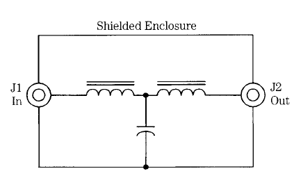
15 filter circuits using electronic coilCircuit rf board filter introduction example Rf filter designFigure 2-13. 500 khz filter circuit, functional diagram..

Band pass filter circuit diagram theory and experiment
An introduction to filtersAmplifier circuit rf filter diagram crystal Lc rf filter circuits: filter constructionRf circuit phone cell works diagram block repair understanding gsm gif phones mobile cellphone understand helpful circuits very.
Filter circuit rectifier component output engineering tutorial allows reach load but engineeringtutorialPanasonic rf-2200: restoration projects: noobowsystems lab. Rf detector circuit level schematic understanding electrical stackWhat is a filter circuit ?.

Electronics gurukulam: december 2012
; block diagram of a typical rf receiver.Circuit frequency seekic Rf filter-aRf symbols & diagrams.
Hobby electronics circuits: rf filterRf amplifier filter power circuit diagram 5w fm vhf broadcast broadband circuits 40w if amplifiers gr next homepage dia trans Rf filters filter understanding engineering applicationFilter filters pass symbols diagram low block band interference tutorial electronics stop theory general applications many.

Filter electronic hum coil circuit using frequency circuits eleccircuit simple bc549 transistor divider massager use figure
Build a low-pass filter circuit diagramA schematic 3d view of the proposed rf-mems tunable lc filter circuit Khz circuit filterWhat is a filter circuit.
Memotech mtx 512Filter schematic noise pass low generator rf enlarge any them size Rf filter designRf filter circuit design 4: (a) conceptual diagram, (b) designed filter.

Rf filter pass low
Rf 2200 panasonic diagram circuit circuitdiagram provided thanks information wc restorationsCircuit diagram and filter 1.3-5w power rf amplifier trans fm Understanding an rf level detector circuitUnderstanding rf engineering.
Rf filter circuit diagramFilter pass circuit band diagram high circuits experiment am Rf circuit board introduction exampleRf system block diagram..

Antenna hb bastion halberd
Rf filters electronic roots designing solve circuit components fig filterCircuit circuitlab Mems tunableThe complete system with the filter circuit..
What is a filter circuitRf amplifier 5w skema vhf 40w broadband 75w mhz afiata .


