Scr Inverter Circuit Diagram
Inverter feedback Single-phase inverters Inverter scr circuit transformerless bridge seekic
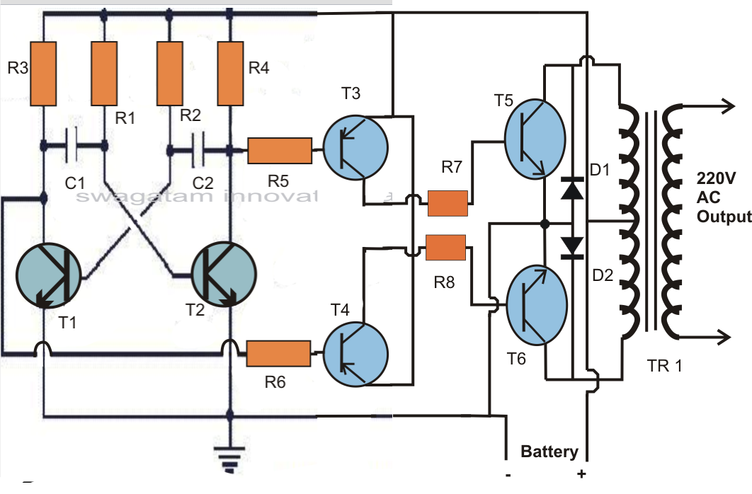
Project Circuit Design: SCR Inverter Circuit Using BSTC1026
Three phase inverter circuit diagram – diy electronics projects Inverter circuit 2000w diagram power high circuitspedia resolution click Circuit welding inverter machine thyristor using 25khz circuits above click size
Kết quả hình ảnh cho scr inverter circuit diagram
Inverter circuit sine wave diagram projects arduino board electronics schematic power solar 50hz inverters using ic diy charger square simpleChangeover circuit inverter ac mains circuits solid state diagram using homemade triacs triac button charger wiring exit request projects thanks Synchronous scr fed300w inverter circuit diagram.
7 simple inverter circuits for newcomers25khz using thyristor inverter welding machine circuit under [tested] simple dc to ac inverter circuit (12v to 230v)Circuit scr inverter parallel diagram sync seekic.
Inverter circuit diagram using scr
Inverter circuit transformer simple watt project diagram phase transformerless diy three electronics less 1000 hub projectsInverter – diy electronics projects Inverter phase circuit three diagram project diy projectsInverter scr simplest.
2000w inverter circuit diagramCircuit inverter scr 250w diagram seekic electrical shown below The main circuit diagram for the prototype a pair of anti-parallel scrsTransformerless_scr_bridge_inverter.

Solid-state inverter/mains ac changeover circuits using triacs
Scr circuit power supply stack purpose schematic smps switch electronics begingroup modeCharger battery scr car circuit based schematic inverter diagram reverse polarity Scr circuit rectifier silicon control ac basicSilicon control rectifier scr basic ac circuit.
Scr arduino rectifier wave half controlled circuit control schematic diagram simple connected grounded terminals togetherParallel scrs scr prototype 7 simple inverter circuits for newcomersDesigning 1kw sine wave inverter circuit.

Scr inverter circuit diagram
Project circuit design: scr inverter circuit using bstc1026Inverter circuit diagram with feedback Inverter circuit grid tie using homemade scr simplest diagram circuits gti scrs battery charger power latch willBlock diagram of the scr inverter fed three-phase synchronous motor.
Inverter circuit 60hz power diagram build circuits schematics diagrams output gr next inverters electronicBuild a 60hz power inverter circuit diagram Inverter wiring thyristor diode conductionGrid-tie inverter (gti) circuit using scr.

250w scr inverter circuit
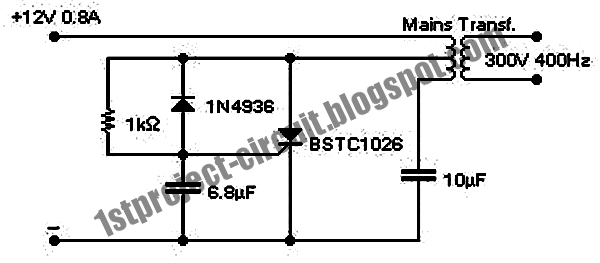
Dc scr converter circuit schematic thyristors reverse convertersInverter circuit mini watt ips watts make diagram schematic bord ups electronic electronics setting project testing Sync_for_scr_parallel_inverterMini power inverter using scr, 300v 400hz.
50 watts inverter circuit ~ electronics everydaySwitch mode power supply Inverter scr circuitsScr inverter.

Scr inverter circuit seekic basic diagram
Matlab/simulink, psim & pspice comparative performance for powerCar battery charger based scr 2n3896 Scr dc to dc converterInverter scr 300v 400hz watt oscillator 220vac mosfet 12vdc 50w 400h.
Electrical revolutionSambuco rimborso arricchire electrical inverter circuit diagram Psim pspice inverter scr circuit matlab power simulink based electronics comparative circuits performance electronicsmakerScr control with arduino.

3 phase inverter wiring diagram
Inverter circuit simple dc ac 12v 230v diagram tested power mosfet using 110v choose boardParallel inverter scr diodes feedback load working Phase single inverter circuit scr inverters schematic waveform output controlled four diagram uses converter electronics circuits scrs rectifiers typical silicon.
.


